Decoder Installation
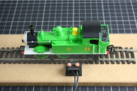
The following guide will aid you with the installation of a standard Hornby decoder into the Thomas & Friends R9070 'Oliver' locomotive.

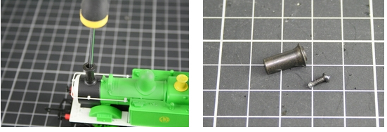
Step 1. Locate and remove the fixing screw from inside the chimney at the front of the locomotive. Place the screw and chimney carefully to one side.
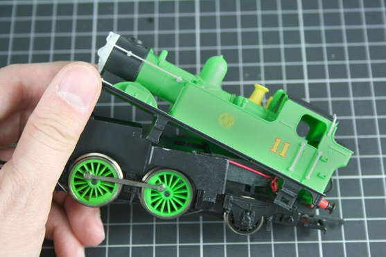
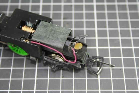
Step 2. Gently pull the front of the chassis down and once it is clear of the body carefully pull the chassis horizontally away from the body.
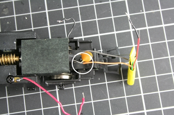
Step 3. Locate the motor at the rear of the chassis which is covered with black card. Protruding from the rear of the motor will be an orange capacitor.
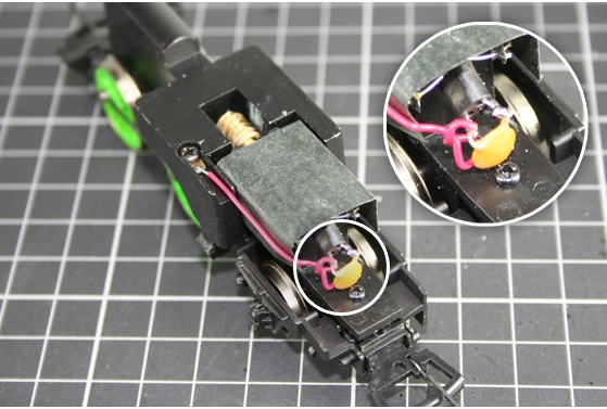
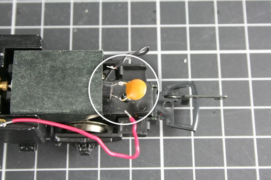
Step 4. Gently loosen the red and black wires from the capacitor so that you can see where they are joined to the capacitor.
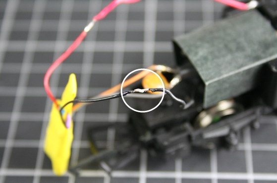
Step 5. Carefully unsolder both the red and black wires from the capacitor as shown.
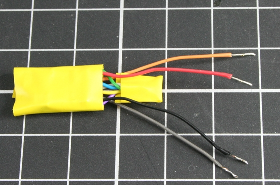
Step 6. Remove the decoder from the protective packaging, taking care not to handle the PCB directly as static electricity will cause irreparable damage. It is important to protect the decoder by wrapping the PCB with insulating tape. To prepare the decoder, remove the plug and separate the red, black, orange and grey wires. The rest can but cut as short as possible and insulated with a piece of insulating tape. Strip the red, black, orange and grey wires and lightly "tin" them with solder. Tinning the wires will make the installation easier. When soldering care must be taken not to breathe in the fumes.
Step 7. Solder the grey wire to the first "leg" of the orange capacitor as shown.
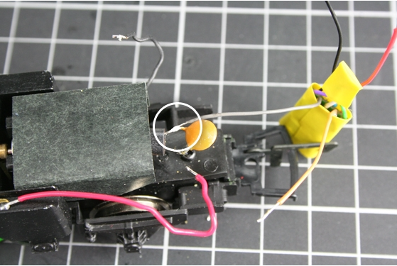
Step 8. Solder the orange wire to the second "leg" of the orange capacitor as shown.
Step 9. Solder the red wire from the decoder to the red pickup wire as shown.
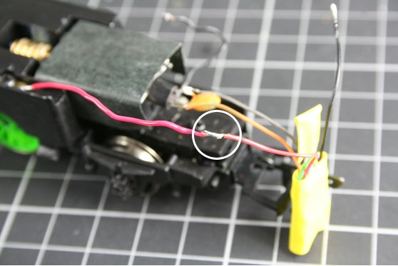
Step 10. Solder the black wire from the decoder to the black pickup wire as shown.
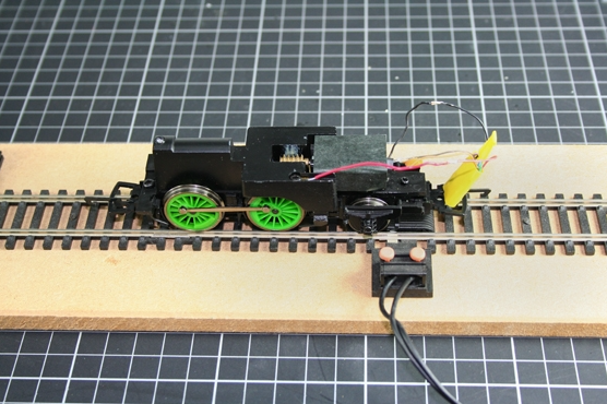
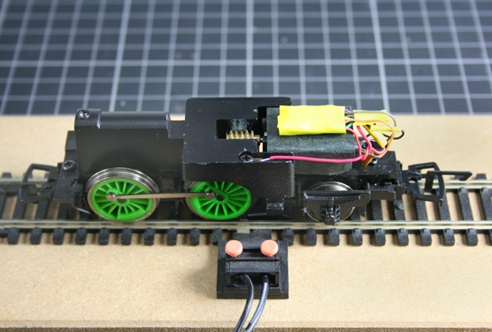
Step 11. Ensure that none of the new joints are touching each other or any metal parts, and place the locomotive onto the programming track and test to make sure that the installation has been successful. Remember that the decoder has a default number of “3” and it is recommended that you code the locomotive to the number you require and test again.
Step 12. Insulate all solder joints as shown and secure the decoder against the locomotives chassis using BlueTack or an other suitable fixative.
Step 13. Place the locomotive onto the test track and test again. Once you are satisfied that the decoder is functioning correctly, replace the loco body, ensuring that there are no wires caught in any moving parts, or 'pinched' between the chassis and the body. Test once more to ensure that the installation has been totally successful.