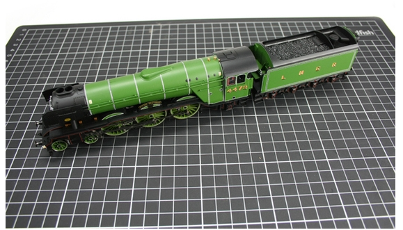
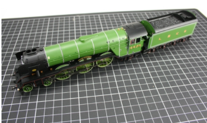
R2441 Flying Scotsman Decoder Installation
The following guide is to assist you with the fitting of a standard Hornby decoder into the R2441 Flying Scotsman locomotive.
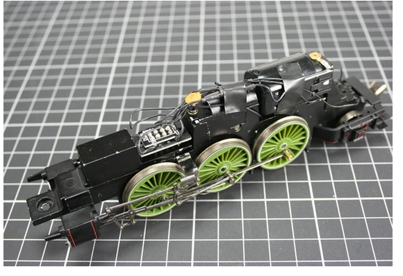
Step 1. Carefully remove the tender and speedometer cable followed by the unscrewing and removing of the front bogie. You will then have access to the main body fixing screw. Gently unscrew this and carefully remove the body by sliding the chassis forwards and gently pull away from the body. It is recommended that you replace the speedometer cable screw back into the wheel to avoid losing any small parts.
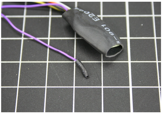
Step 2. Remove the decoder from the protective packaging, taking care not to handle the PCB directly as this will cause irreparable damage due to static electricity. It is important to protect the decoder by wrapping the PCB with insulating tape. However, the R2441 Flying Scotsman is supplied with a piece of insulating sleeve which is designed to slip over the PCB and will protect the decoder
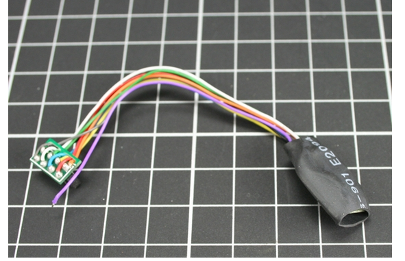
Step 3. Using a small piece of insulting tape cover the bare end of the purple wire, however this wire maybe shortened if you require.
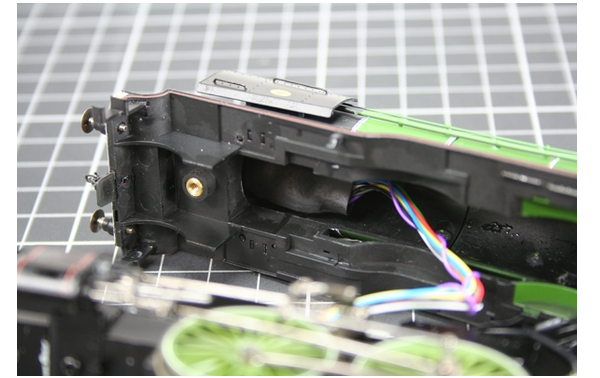
Step 4. Locate the decoder blanking plate situated between and above the front driving wheels. Carefully, lever off the blanking plate from it’s socket ensuring that you do not damage the surrounding components.
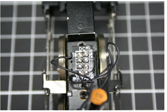
Step 5. With the blanking plate removed an 8 pin socket is now visible. Note the location of “Pin 1” indicated by the number “1” and an “Arrow” printed onto the socket.
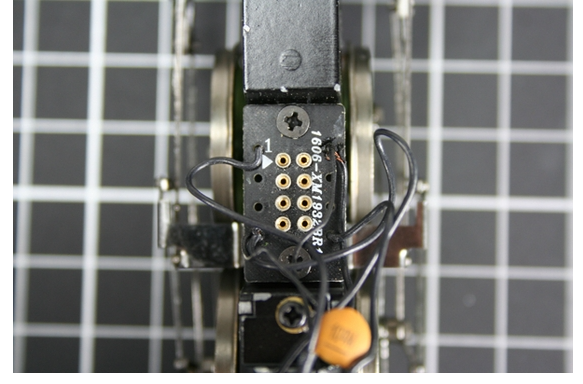
Step 6. Carefully insert the decoder so that the pin connected to the orange wire is inserted into Pin 1. Make sure all pins are properly located before pressing home.
Step 7. Once the decoder is located, place the locomotive on the programming track and test to make sure that the installation has been successful. Remember that the decoder has a default number of “3” and it is recommended that you code the locomotive to the number you require and test again.
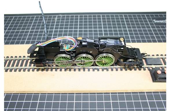
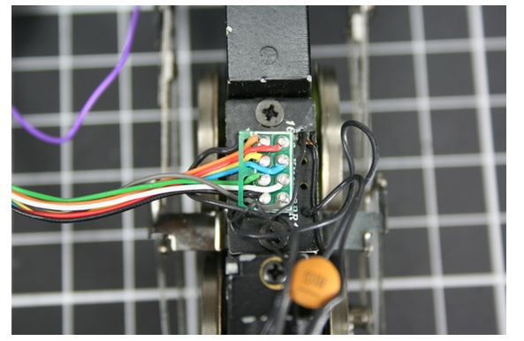
Step 8. Once you are satisfied that the decoder is functioning correctly locate it in a suitable aperture ensuring that it is away from moving parts. Once installed, carefully position all wires so that they do not touch any moving parts. Use insulating tape if required.
Step 9. Carefully replace the body onto the chassis taking care not to trap any wires during this procedure. Replace the body retaining screw followed by the front bogie, speedo meter cable and then finally the tender. Test once more to ensure that the installation was totally successful. It is easier to reattach the speedometer cable if the screw fixing on the wheel is at the 7 o'clock position.