R2506 BR (late) 0-4-4T Class M7 Decoder Installation
The following guide is to assist you with the fitting of a standard Hornby decoder into the R2506 BR (late) 0-4-4T Class M7 locomotive.
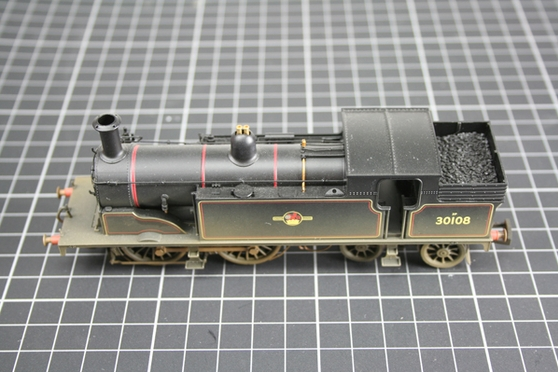
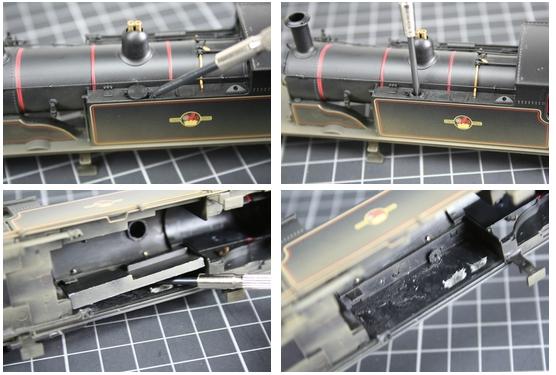
Step 1. Carefully remove the locomotive body taking great care not to damage delicate fittings. The rear bogie must be carefully moved sideways to access the body fixing screw.
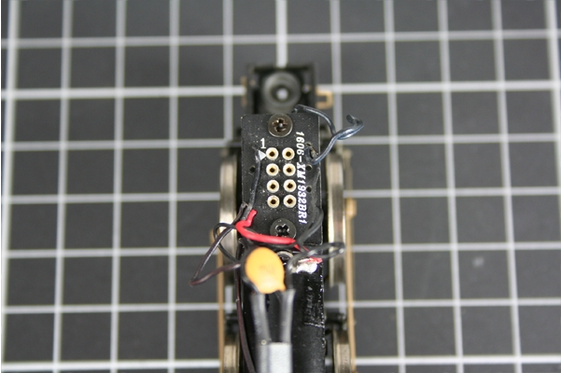
Step 2. Locate the decoder blanking plate situated above the front driving wheels. Carefully, lever off the blanking plate from it’s socket ensuring that you do not damage the surrounding components.
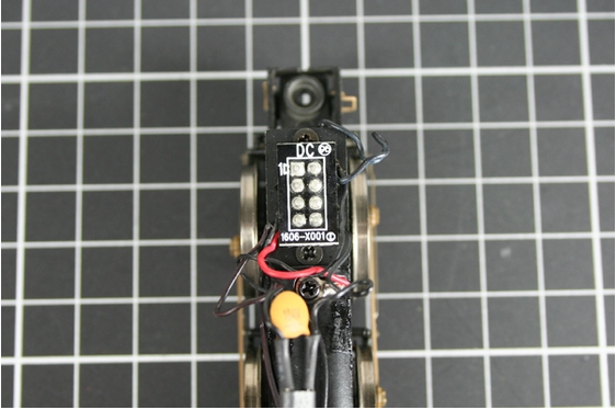
Step 3. With the blanking plate removed an 8 pin socket is now visible. Note the location of “Pin 1” indicated by the number “1” and an “Arrow” printed onto the socket.
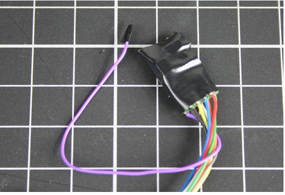
Step 4. Remove the decoder from the protective packaging, taking care not to handle the PCB directly as this will cause irreparable damage due to static electricity. It is important to protect the decoder by wrapping the PCB with insulating tape. Using a small piece of insulting tape cover the bare end of the purple wire, however this wire maybe shortened if you require.
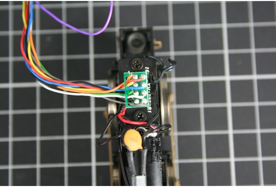
Step 5. Carefully insert the decoder so that the pin connected to the orange wire is inserted into Pin 1. Make sure all pins are properly located before pressing home.
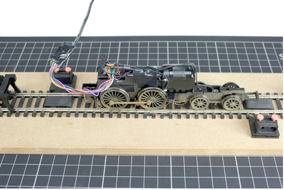
Step 6. Once the decoder is located, place the locomotive on the programming track and test to make sure that the installation has been successful. Remember that the decoder has a default number of “3” and it is recommended that you code the locomotive to the number you require and test again.
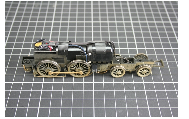
Step 7. To make room for the decoder, a lead weight must be removed from the side of the loco body. To do this you must first remove the left hand water filler cap. Carefully slide a small screwdriver under the lip and prise it off, then remove the small screw that holds the lead weight in the water tank. Once this is removed, the lead weight will be loose enough to work free with a screwdriver. You can now refit the water tank filler cap. Please take great care during this operation.
Step 8. Ensuring the the wires are laying flat and spread evenly over the top of the motor, place the decoder into the space made by removing the weight, and fix using Blue tack or a suitable fixative.
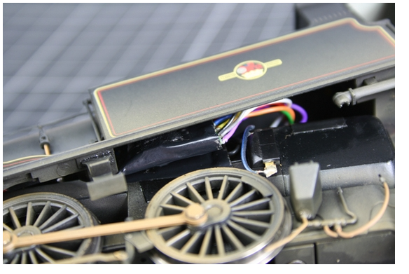
Step 9. As you replace the body and if the decoder has been fitted correctly, the decoder will sit inside the water tank with the wires positioned away from moving parts.
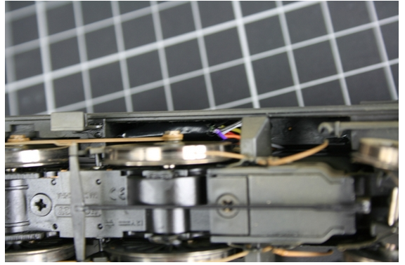
Step 10. Replace the retaining screw and test to ensure wires and decoder will not foul on the wheels or motor, and test again.